Photocell is dual zone type. Black white red red 120 / 277 / 347 v~ 60 hz;
Nlight Wiring Diagram
Cap off the red wire on all packs other than the first pack.

Nlight power pack wiring diagram. This power is typically utilized by other nlight devices within the power pack's local control zone; Turn power off before wiring. And the power pack tracks (obeys) switch status changes on channel 1.
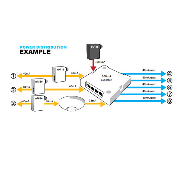
Select power packs provide +24vdc low voltage output to power up to 4 nlight air mounted occupancy sensors and photocells. Refer to the appropriate wiring diagram below. Diagram] need fuses for nlight power pack full version hd uploaded by admin on saturday, october 24th, 2020 in category diagram.
See also emergency lighting control: Locate and lock the supply breaker in the off position, or remove the supply fuse before proceeding. The newly released nlight catalog contains comprehensive product information.
The nlight air rpp is designed for use as part of an nlight air group of devices or with the nlight eclypse™. Nsp5 pcd 2w secondary pack; 230 v~ 50 / 60 hz
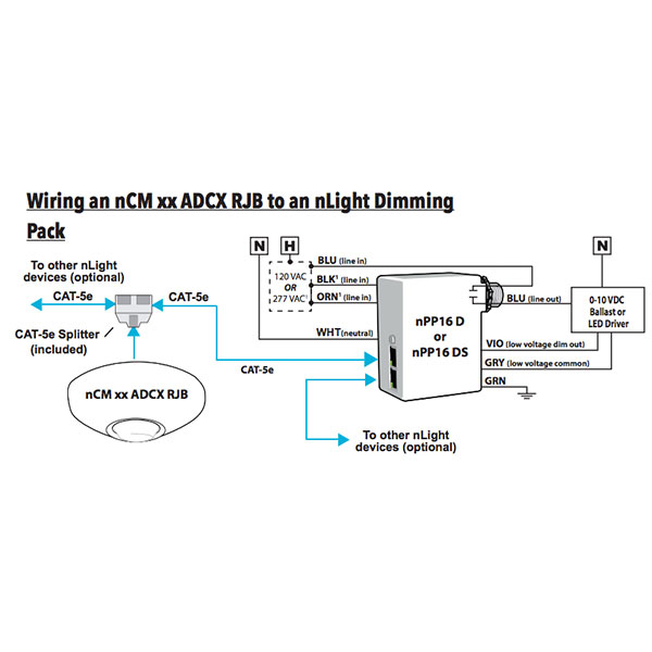
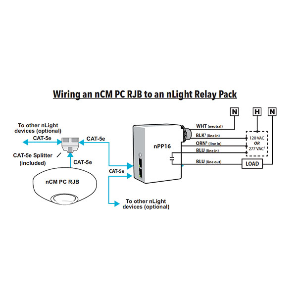
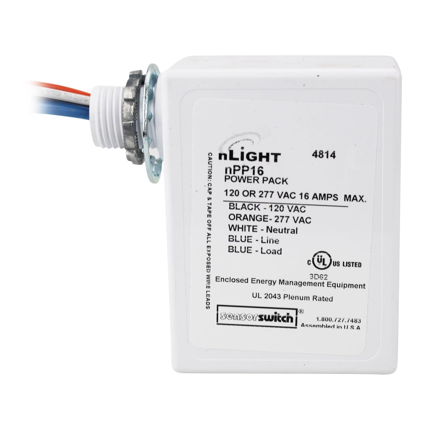
Wiring power pack wiring the power pack depends on the application and the line voltage. To provide system power, the power pack transforms class 1 line voltage (120/277 vac or 347 vac) to class 2 15 vdc. The nlight npp16 series power pack is the workhorse of an nlight system.
This table shows default broadcast (status) channels for a sampling of nlight wallpod switches, and default tracking (listening) channels for common power pack devices; Home » nlight » nlight power relay pack instruction manual nlight power relay pack contents [ hide 1 specifications (rpp20) 2 overview 3 installation instructions 3.1 required tools & supplies 3.2 installation steps 4 troubleshooting tips 5 user button 6 wiring (do not wire hot) 7 file downloads 8 references 9 related manuals. Here we have another image acuity controls nlight npp16 er efp emergency power/ relay sensor.
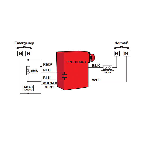
Nlight emergency power pack wiring diagram is just what we at to share to you. Connecting more than one power pack when required for increased load capacity or to control multiple voltages with one sensor, uvpp or uvppm power packs can be connected as shown in the wiring digram below. Each unit has two important responsibilities:
Normal power feed is lost the npp16 (d) erwill override its relay sequence of operation of standard units is auto on/auto off. Never ever stress not to discover exactly what you require. This section includes a set of fixture connection diagrams, each with a similar format:
16 amp npp16 d efp power/relay pack; Plug load control diagram 1 nef nef emg nef emg nef nef nef. Devices with 2p or 4p indicate multiple.
It will be done by providing the right choice of you to think that analysis is always required. Pdf download nlight power pack wiring diagram. Later than frustrating to remove, replace or fix the wiring in an automobile, having an accurate and detailed nlight.
What is nlight nlight is a revolutionary digital architecture and networking technology that cost effectively integrates time based daylight based sensor based ppt video online download from slideplayer.com 2 pack of lights and 1 transformer jul 13, 2021 · the biggest drawback to even the best outdoor floodlight is that it may require wiring to power the light. Maximum of 3 devices total (occupancy sensors and auxiliary power packs) can be connected to a power pack. Nlight power pack wiring diagram.
Right out of the box, the npodm can control the room's lighting. Every nlight zone has 16 channels of occupancy, 16 channels of photocell, and 16 switch channels on which to communicate information (see diagram). Nlight relay panel wiring diagram.
Book fans, when you need an extra book to check out, find the book nlight power pack wiring diagram right here. Ceiling mounted occupancy +photo sensor. Do not connect the red (+24vdc) wires together.
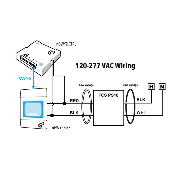
The nlight quick reference guide brings you the best of nlight in a simple,. Shunt relay, automatic load control relay and automatic transfer switch. An example of a typical nlight zone is an office lobby with an nlight occupancy sensor, power/relay pack, and wall switch controlling the lighting.
A unique conceptual diagram that describes the location and relationships of the power and control feeds, junction boxes, nlight devices, sensors This book will certainly not obligate you to even review the book specifically. Providing system power and switching lighting loads.
Power pack features • on/off and dimming control of a luminaire or group of luminaires • 24vdc output to. However, remaining power is also made.

Floureon Camera Wiring Diagram

Npp16 D Er Efp Wiring Diagram
Nlight Wiring Diagram

N Light Wiring Diagram Honda Civic Ek Fuse Box Diagram
nBRG 8 nLIGHT BRIDGE 8 PORT LiteRite Controls
Patent US8731689 Networked, wireless lighting control


Watt Stopper Power Pack Wiring Diagram
[View 21+] Nlight Relay Panel Wiring Diagram
Nlight Wiring Diagram

Npp16 D Er Efp Wiring Diagram

Nlight Wiring Diagram
Nlight Wiring Diagram

Power At Light Wiring Diagram Wiring Sample
NCM PC RJB nLIGHT DAYLIGHT SENSOR PRIMARY & SECONDARY

[View 21+] Nlight Relay Panel Wiring Diagram
Nlight Controls Wiring Diagram Normal / Emergancy Relays
nGWY2 KIT nLIGHT GATEWAY DEVICE W/ TOUCHSCREEN & CONTROL

Power At Light Wiring Diagram Wiring Sample

Npp16 D Er Efp Wiring Diagram


