Wednesday, October 19, 2022

Honda Gx390 Starter Switch Wiring Diagram

Honda Gx390 Starter Switch Wiring Diagram

nest Hello Wiring Diagram, Nest Hello Advanced Wiring Diagram, 6.25 MB, 04:33, 63,749, gt8monster, 2018-06-16T10:14:46.000000Z, 19, Nest Hello Doorbell: 18 Questions/Answers You Need To Know - Smart Home Point, www.smarthomepoint.com, 1057 x 852, png, nest diagram hello doorbell wiring google camera chimes chime install multiple lh4 googleusercontent answers questions know need pre, 20, %ef%bb%bfnest-hello-wiring-diagram, Anime Arts

77 lovely honda gx390 starter wiring diagram. Here's what to do:first you infatuation to acquire the pass starter out. Sometimes it's simple and sometimes not. The only excuse it might be hard is if it's located in a strange place.

This diagram will also help you understand how the engine works and how to properly wire it for an electric start. Wiring diagram switch honda gx390 ignition electric start starter motorcycle wire generator club golf ez cart key coil diagrams solutions. Now you have done the installation process. To properly read a electrical wiring diagram, one offers to learn how the particular components in the system operate. Honda gx390 starter wiring diagram. To properly read a electrical wiring diagram, one offers to learn how the particular components in the system operate. For instance , if a module is usually powered up and it sends out a new signal of half the voltage and the technician will not know this, he would think he has a challenge, as he would expect. Wiring diagram switch honda gx390 ignition electric start starter motorcycle wire generator club golf ez cart key coil diagrams solutions. Honda wiring gx390 diagram starter electric start switch engine petrol gx270 5hp wire motor gx200.

Honda Gx390 Ignition Coil Wiring

Honda Gx390 Ignition Coil Wiring
Image by schematron.org

Honda Gx390 Electric Start Wiring Diagram | Wiring Diagram
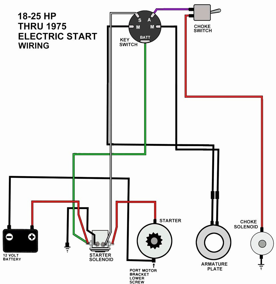
Honda Gx390 Electric Start Wiring Diagram | Wiring Diagram
Image by annawiringdiagram.com

17+ Honda Gx390 Engine Wiring Diagram - Engine Diagram in 2020 | Honda, Diagram, Electricity

17+ Honda Gx390 Engine Wiring Diagram - Engine Diagram in 2020 | Honda, Diagram, Electricity
Image by www.pinterest.com

Wiring Diagram For A Honda Gx390 Electric Start

Wiring Diagram For A Honda Gx390 Electric Start
Image by wiringall.com

Honda Gx390 Wiring Diagram | Wiring Diagram
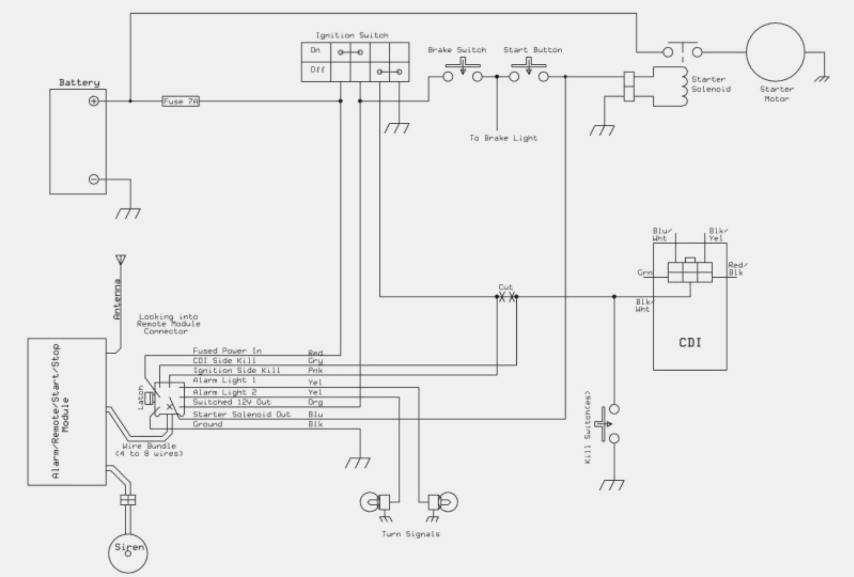
Honda Gx390 Wiring Diagram | Wiring Diagram
Image by annawiringdiagram.com

Honda Gx390 Starter Wiring Diagram Simple Honda Gx390 Electric Start Wiring Diagram Honda, 125

Honda Gx390 Starter Wiring Diagram Simple Honda Gx390 Electric Start Wiring Diagram Honda, 125
Image by tonetastic.info

19 Elegant Honda Gx390 Wiring Diagram

19 Elegant Honda Gx390 Wiring Diagram
Image by bosco-mylove.blogspot.com

Honda Gx390 Electric Start Wiring Diagram Images - Wiring Diagram Sample

Honda Gx390 Electric Start Wiring Diagram Images - Wiring Diagram Sample
Image by faceitsalon.com

Honda Gx390 Electric Start Wiring Diagram

Honda Gx390 Electric Start Wiring Diagram
Image by wiringall.com

Honda Gx390 Wiring Diagram | Wiring Diagram
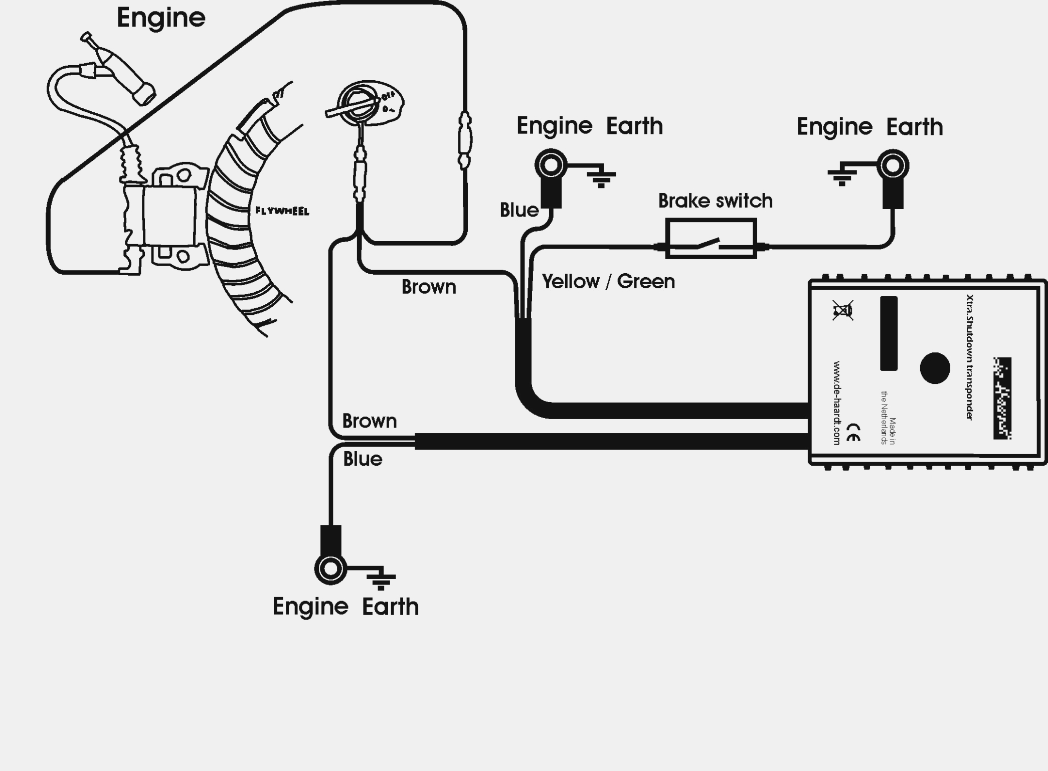
Honda Gx390 Wiring Diagram | Wiring Diagram
Image by annawiringdiagram.com

Tuesday, October 18, 2022

Incredible Diagram For Wiring A Three Way Switch Ideas

Incredible Diagram For Wiring A Three Way Switch Ideas. The best way to understand wiring diagrams is to. A three conductor cable goes from one switch box to the.

Wiring Diagrams
Wiring Diagrams from maliburacing.com

The circuit comprises three main wires: 3 wire alternator wiring diagram source: For instance , if a module is usually powered up and it sends out a new signal of half the voltage and the technician will not know this, he would think he has a challenge, as he would expect the 12v signal.

Sometimes It Is Handy To Have An Outlet Controlled By A Switch.


Line power is delivered to the first switch by using a two conductor cable with a bare or green equipment grounding conductor. Toggle switch, stops the flow of current when open; Typical standard fender stratocaster guitar wiring with master volume plus 1 neck tone control and one middle pickup tone control.

I Use The 4 Way With My Tele Clone (Tokai).


This guitar wiring diagram is property of guitarelectronics.com inc. Mar 09, 21 09:56 pm. 1st method is to get a small paper clip and insert it in the small hole by each labeled (numbered) terminal and release the tension clip and pull the wire out.

Don't Forget The Wire, Solder, Shielding &;


Click diagram image to open/view full size version. Wire sizes on these and most other wiring diagrams are printed on the wire in mm 2.for americans who express wire sizes in gauges, see this wire size conversion table. An antenna is a straight line with three small lines branching off at its end, much like a real antenna.

Its Fun To Have A 'More Oomph' Setting Available One Of My Fav Tele Wirings Is Very Unorthodox.


The circuit comprises three main wires: Options for north/south coil tap, series/parallel & more. 2 way switch (3 wire system, old cable colours) 2 way switch (two wire control) three way switching.

This Will Be Accomplished With The Use Of Three Parts And Some Trick Wiring.


Fig 5 shows the same connection to control a light point from three places by using different symbols. The ignition input wire is attached to the engine. You can observe in the schematic that both the com terminals are connected together.

S10 Wiring Diagram Pdf

S10 Wiring Diagram Pdf

nest Hello Wiring Diagram, Nest Hello Advanced Wiring Diagram, 6.25 MB, 04:33, 63,749, gt8monster, 2018-06-16T10:14:46.000000Z, 19, Nest Hello Doorbell: 18 Questions/Answers You Need To Know - Smart Home Point, www.smarthomepoint.com, 1057 x 852, png, nest diagram hello doorbell wiring google camera chimes chime install multiple lh4 googleusercontent answers questions know need pre, 20, %ef%bb%bfnest-hello-wiring-diagram, Anime Arts

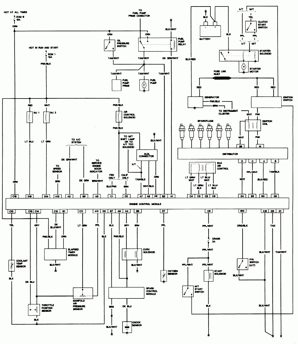
Få adgang til alle ledningsdiagrammer bil. 2500hd [diagram] 1999 s10 wiring diagram pdf firediagram. blogspot. com. Chevy s10 wiring schematic. Trailblazer 2002 diagram wiring chevy chevrolet drive 4wd wheel diagrams parts responding guide 2005.

95 s10 turn signal wiring diagram. Diagram wiring ezgo club switch micro 1994 gas golf cart raw. Truck has been running fine, one. Truck has been running fine, one : 2000 s10 wiring diagram pdf : Instrument 2001 cluster wiring panel schematic gauges s10 diagram repair console guides autozone 2000 indicators fig sonoma pickup. Diagram wiring throttle body s10 1989 chevy 1500 1996 engine truck pulse k1500 motor chev clutch grounds pump went bad. 01 s10 fuel pump wiring diagram wiringmanualpdf. blogspot. com. Fuel pump s10 wiring diagram chevy 1997 2000 relay wire chevrolet schematic problems 2carpros manual pdf.

S10 Wiring Diagram Pdf | Wiring Diagram

S10 Wiring Diagram Pdf | Wiring Diagram
Image by annawiringdiagram.com

2000 Chevy S10 Wiring Diagram - I have a 2000 chevrolet s10 that had a 2.2 4cyl in it with flex

2000 Chevy S10 Wiring Diagram - I have a 2000 chevrolet s10 that had a 2.2 4cyl in it with flex
Image by wiring08.blogspot.com

Wiring Manual PDF: 01 S10 Wiring Schematic

Wiring Manual PDF: 01 S10 Wiring Schematic
Image by wiringmanualpdf.blogspot.com

S10 Wiring Diagram Pdf / S10 91 Pdf Pickup Truck Cars Of The United States - 81% (16) 81% found

S10 Wiring Diagram Pdf / S10 91 Pdf Pickup Truck Cars Of The United States - 81% (16) 81% found
Image by wiring05.blogspot.com

S10 Wiring Diagram Pdf | Wiring Diagram

S10 Wiring Diagram Pdf | Wiring Diagram
Image by annawiringdiagram.com

1987 S10 2.5L wiring - S-10 Forum

1987 S10 2.5L wiring - S-10 Forum
Image by www.s10forum.com

S10 Wiring Diagram Pdf Inspirational | Chevy, Chevrolet, Diagram

S10 Wiring Diagram Pdf Inspirational | Chevy, Chevrolet, Diagram
Image by www.pinterest.com

2000 S10 Wiring Diagram Pdf / Chevrolet Car Pdf Manual Wiring Diagram Fault Codes Dtc : Provides

2000 S10 Wiring Diagram Pdf / Chevrolet Car Pdf Manual Wiring Diagram Fault Codes Dtc : Provides
Image by gmdlbp-wiring-diagram.blogspot.com

[DIAGRAM] 1999 S10 Wiring Diagram Pdf

[DIAGRAM] 1999 S10 Wiring Diagram Pdf
Image by firediagram.blogspot.com

1999 Chevy S10 Electrical Diagram Full Version

1999 Chevy S10 Electrical Diagram Full Version
Image by cafeconmostaza.blogspot.com

Sunday, October 16, 2022

Well Pump Float Switch Wiring Diagram

Well Pump Float Switch Wiring Diagram

Rj11 Socket Wiring Diagram Australia, How to punch down an RJ11 Telephone Jack, 6.36 MB, 04:38, 387,634, CableSupply.com, 2009-08-05T00:16:07.000000Z, 19, Rj11 Socket Wiring Diagram Australia | Computacion, Redes de computadoras, Computadoras, www.pinterest.com.mx, 728 x 783, jpeg, rj11 wiring rj45 diagram cable ethernet usb jack pinout adapter cat5 female male convert using rs485 cat wires code socket, 20, rj11-socket-wiring-diagram-australia, Anime Arts

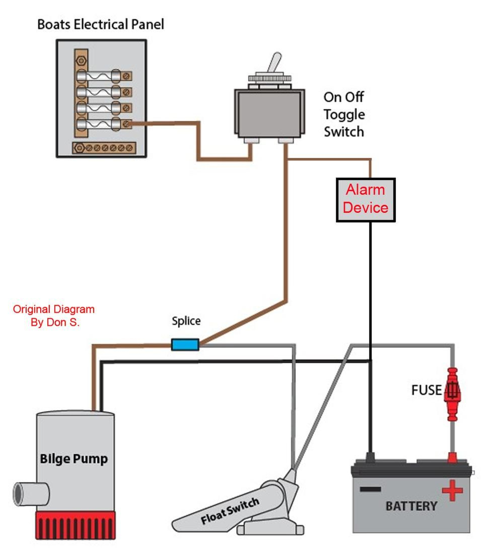
This is explained with a circuit diagram. This video shows how to connect 2 float switches to the water pump. This circuit is prepared for water pump safety. A float switch is a mechanical switch that floats on top of a liquid surface.

Septic pump float switch wiring diagram gallery. A wiring diagram is an easy visual. But loose connections behave like speed bumps, restricting the flow and creating friction as well as heat. Very loose connections can cause arcing, where electricity jumps with the air. Remember that what you're wiring is a means of turning things on and off. This thinking will help you as you visualize the float switch connection and apply the schematic to real world control. We're going to look at a progression of straightforward pump control arrangements using float switches. We'll look at switch writing diagrams and. Float switch wiring diagram for single phase water pump | float switch connection |#learning_engineering#konok_kamruzzaman #learning_engineering_online_schoo.

float switch wiring diagram for water pump - YouTube

float switch wiring diagram for water pump - YouTube
Image by www.youtube.com

Septic Pump Float Switch Wiring Diagram | Free Wiring Diagram

Septic Pump Float Switch Wiring Diagram | Free Wiring Diagram
Image by ricardolevinsmorales.com

3 Wire Float Switch Wiring Diagram - easywiring

3 Wire Float Switch Wiring Diagram - easywiring
Image by easywiring.info

Bilge Pump Float Switch Wiring Diagram | Cadician's Blog

Bilge Pump Float Switch Wiring Diagram | Cadician's Blog
Image by 2020cadillac.com

I'm looking to hook up a well pump to turn on by a float switch similar to your previous answer

I'm looking to hook up a well pump to turn on by a float switch similar to your previous answer
Image by www.justanswer.com

Water Pump Auto/Manual Control | Float Switch Wiring Diagram | Water Well Float Switch

Water Pump Auto/Manual Control | Float Switch Wiring Diagram | Water Well Float Switch
Image by www.youtube.com

35 Float Switch Wiring Diagram - Wiring Diagram Database

35 Float Switch Wiring Diagram - Wiring Diagram Database
Image by kovodym.blogspot.com

Single Ball Float Switch Wiring Diagram Bosch Dishwasher Water And Remarkable Septic Tank 11

Single Ball Float Switch Wiring Diagram Bosch Dishwasher Water And Remarkable Septic Tank 11
Image by www.pinterest.com

Wiring for Dual Float Switch System; Well (high level ON), cistern (lo

Wiring for Dual Float Switch System; Well (high level ON), cistern (lo
Image by www.sumpalarm.com

230v Float Switch Wiring Diagram

230v Float Switch Wiring Diagram
Image by coveredinsparkles.blogspot.com

Saturday, October 15, 2022

7 Wire Trailer Plug Wiring Diagram

7 Wire Trailer Plug Wiring Diagram

nest Hello Wiring Diagram, Nest Hello Advanced Wiring Diagram, 6.25 MB, 04:33, 63,749, gt8monster, 2018-06-16T10:14:46.000000Z, 19, Nest Hello Doorbell: 18 Questions/Answers You Need To Know - Smart Home Point, www.smarthomepoint.com, 1057 x 852, png, nest diagram hello doorbell wiring google camera chimes chime install multiple lh4 googleusercontent answers questions know need pre, 20, %ef%bb%bfnest-hello-wiring-diagram, Anime Arts

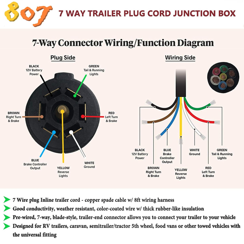
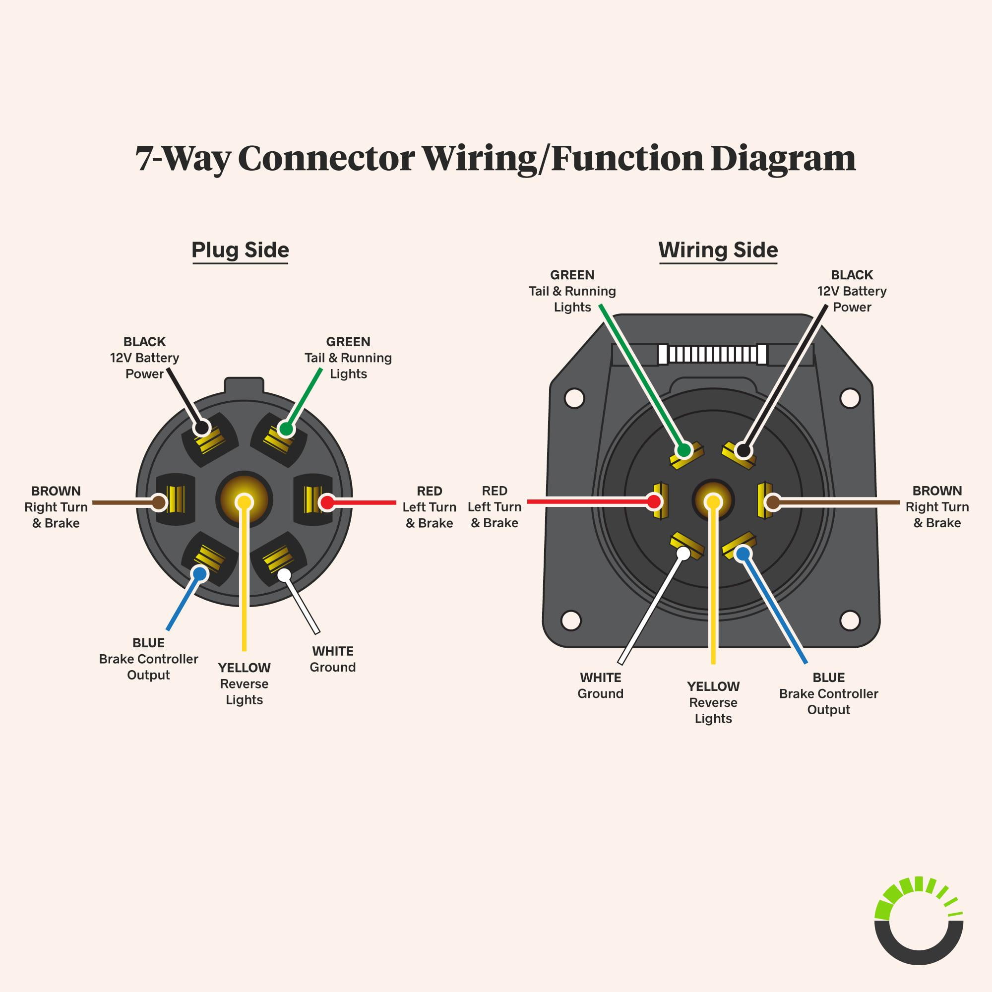
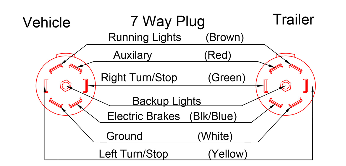
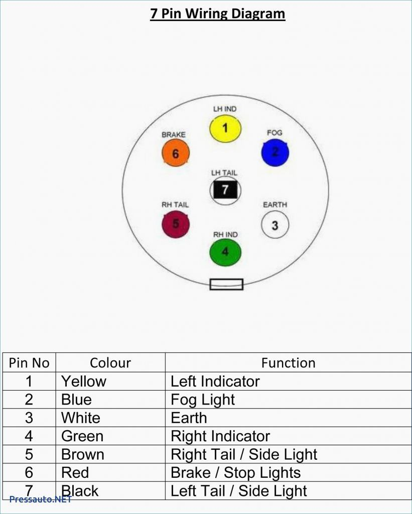
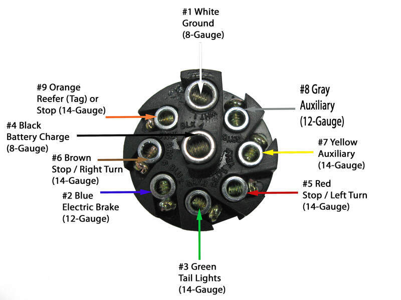
If you are looking at the inside of the trailer connector where the wires mount to the terminals starting at the top and rotating clockwise: 1:00 is black and 12 volt power. 3:00 is green and right turn and brake. 5:00 is blue and brake controller.

9:00 is yellow and left turn and brake. 7 way trailer plug wire colors, seven wire trailer diagram. Rv wiring diagram battery batteries sandpiper jayco tips 1992 generator wheel trailer camper electrical water motorhome maintenance maintain fifth 5th 7 way plug wiring diagram standard wiring* post purpose wire color tm park light green (+) battery feed black rt right turn/brake light brown lt left turn/brake light red s trailer electric brakes blue gd ground white a accessory yellow this is the most common (standard) wiring scheme for rv plugs and the one used by major auto manufacturers today. Following the standard method for wiring a trailer connector is vital to the safety of your vehicle while towing. Connecting the wrong color wires will result in mismatched taillight functions and confusion on the road. • green right turn / brakes. Trailer plug wiring diagram round connector hopkins blade ford way south africa pollak sabs trusted pole standard for6 today wire. 7 pole round trailer plug wiring diagram free download 2022 by dexter. wehner.

7 Way Trailer Plug Wiring Diagram | Wiring Diagram

7 Way Trailer Plug Wiring Diagram | Wiring Diagram
Image by wiring-diagram.net

Wiring Diagram On 7 Way Trailer Plug | Trailer Wiring Diagram

Wiring Diagram On 7 Way Trailer Plug | Trailer Wiring Diagram
Image by trailer-wiring-diagram.com

7 Way Connector Diagram / Dodge 7 Way Trailer Wiring Color Wiring Diagram Home Just Fold Just

7 Way Connector Diagram / Dodge 7 Way Trailer Wiring Color Wiring Diagram Home Just Fold Just
Image by wiring05.blogspot.com

Trailer Plug Wiring Diagram 7 Way Flat | Trailer Wiring Diagram

Trailer Plug Wiring Diagram 7 Way Flat | Trailer Wiring Diagram
Image by trailer-wiring-diagram.com

Heavy Duty 7 Way Trailer Plug Wiring Diagram | just wiring

Heavy Duty 7 Way Trailer Plug Wiring Diagram | just wiring
Image by wiringhq.blogspot.com

Plug Wiring Diagram | Double A Trailers

Plug Wiring Diagram | Double A Trailers
Image by doubleatrailers.ca

[DIAGRAM] Herchr Us Standard Trailer Plug 12v 7 Way Pin Rv Blade To Wiring Diagram FULL Version

[DIAGRAM] Herchr Us Standard Trailer Plug 12v 7 Way Pin Rv Blade To Wiring Diagram FULL Version
Image by ldiagrams.tiburmedical.it

7 Way Trailer Plug Wiring Diagram Gmc - Cadician's Blog

7 Way Trailer Plug Wiring Diagram Gmc - Cadician's Blog
Image by 2020cadillac.com

Ford 7 Pin Trailer Wiring Diagram | Cadician's Blog

Ford 7 Pin Trailer Wiring Diagram | Cadician's Blog
Image by 2020cadillac.com

Trailer Wiring Pigtail - 7 Way Trailer Plug Wiring Diagram : I think it's on the passenger side

Trailer Wiring Pigtail - 7 Way Trailer Plug Wiring Diagram : I think it's on the passenger side
Image by schematicdiagram20.blogspot.com

Incredible Sugar Free Dessert Shop Near Me 2022

Incredible Sugar Free Dessert Shop Near Me 2022 . Maintaining a no sugar added (nsa) or low carb diet is hard enough, without giving up your...